Resolver Engineering
Introduction
Basic Mechanism of a Resolver
A motor resolver is a type of rotation angle sensor for controlling the drive motor that is the power source of EVs. By efficiently controlling the motor, power consumption can be suppressed. To control the motor according to various driving conditions of a vehicle, it is necessary to detect the magnetic pole position of the motor and accurately grasp its rotational speed. The resolver serves as a sensor for these tasks.

Structure of a Resolver
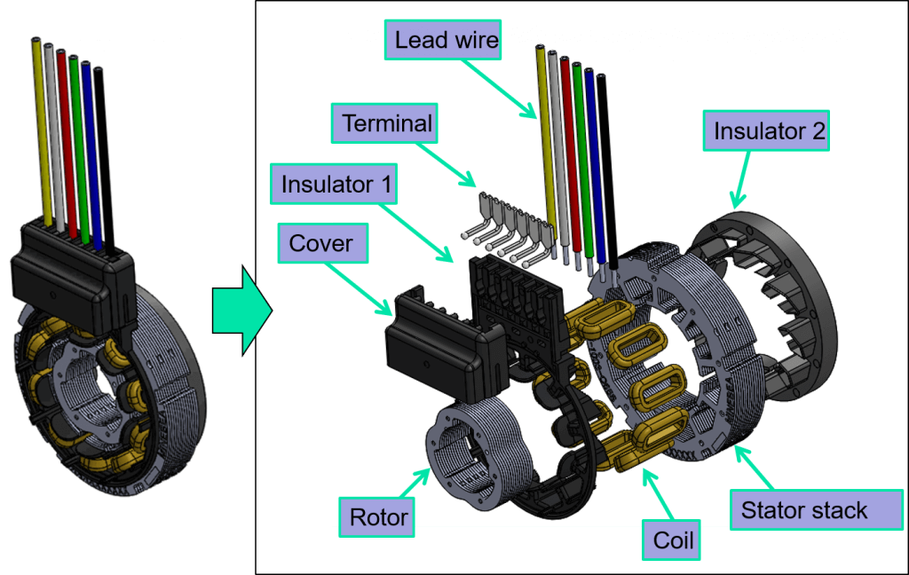
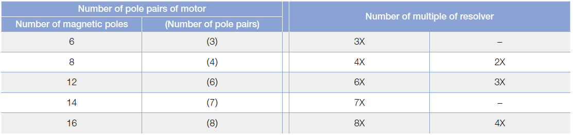
The number of motor pole pairs will have a direct influence on the multiple of the rotor. The resolver is a vital sensor for ensuring the proper operation of the EV motor. The advanced design of the rotor lobes is optimized for high-accuracy angle detection, increasing the motor’s efficiency.
Selecting a Resolver

Mounting Method
Fixing method of small-diameter resolver
Stator mounting method (fixed plate)
- Mount to the housing in a loose fitting.
- Do not fix by press fitting.
- Fix the stator by fastening it with the fixing plate using bolts and nuts.
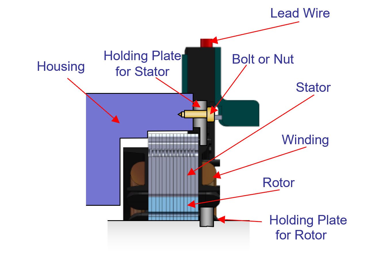
Rotor mounting method
- Mount to the shaft either in a loose fitting or press fitting. If the rotor has been fit in a loose fitting, fix the rotor by fastening it with the fixing plate using bolts and nuts.
- Do not perform press fitting that will deform the rotor.

Fixing method of large-diameter resolver (Bigger than 40VRX)
Mounting method of stator and rotor
- Fix the stator in a loose fitting with the coaxiality of the rotor (Recommendation: 0.1mm or less). Mount the rotor either in a loose fitting or by press fitting.
- Fix the stator to the housing with bolts and nuts, etc. using fixing holes.
- If the rotor has been fit in a loose fitting, fix it by fastening the rotor with the fixing plate using bolts and nuts.
- Do not perform press fitting that will deform the rotor. Doing so may degrade the accuracy.
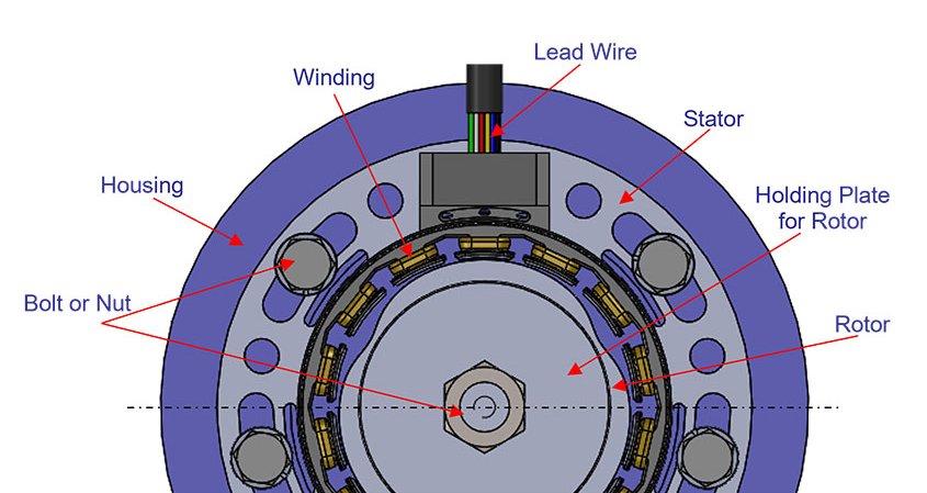
- Fix the rotor and the stator using the fixing plate with bolts and nuts.
- Use your hands or a press when mounting the rotor and stator so that the product does not tilt. Do not strike the product with a hammer, etc. Doing so may degrade the electrical characteristics.
- Be careful not to damage the winding while performing work. Damaging the winding may result in the wire breaking or an insulation failure.
Principle of Angle Detection
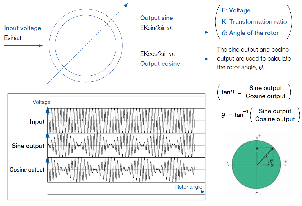
The resolver principle of angle detection is based on the calculation from the sine and cosine output signals. The multiple of the rotor and the shape of the rotor lobes are optimized to provide high accuracy readings, allowing the motor to operate with higher efficiency.
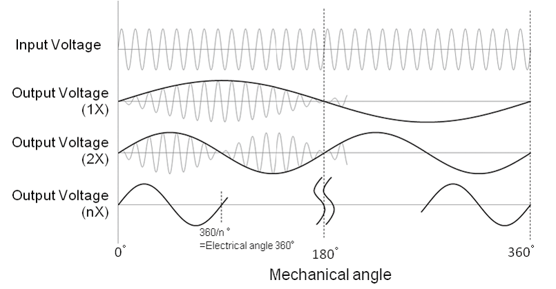
Relation Between Number of Rotor Lobes and Signal Multiple

The number of multiples from the rotor and the shape of the rotor lobes are optimized to provide high accuracy readings, allowing the motor to operate with higher efficiency. The higher the number of multiples for the rotor, the higher the accuracy will be.
Selecting the Resolver Multiple Based on BLDC Motor Pole Pairs
Environmental Durability - Typical Testing
| Test Type | Inspected Items |
|---|---|
| High-temperature storage test | Electrical characteristics, appearance (resin portion, rust, varnish, welded portion) |
| Low-temperature storage test | Electrical characteristics, appearance (resin portion, rust, varnish, welded portion) |
| High-temperature and high-humidity storage test | Electrical characteristics, appearance (resin portion, rust, varnish, welded portion, terminal) |
| Thermal cycle test | Electrical characteristics, appearance (resin portion, rust, varnish, welded portion, terminal) |
| Sweep vibration test (X, Y, and Z) | Electrical characteristics, appearance (wire binding portion, welded portion, loose portion, stack, resin portion) |
| Impact test (X, Y, and Z) | Electrical characteristics, appearance (wire binding portion, welded portion, loose portion, stack, resin portion) |
Lead Wire Tensile Strength

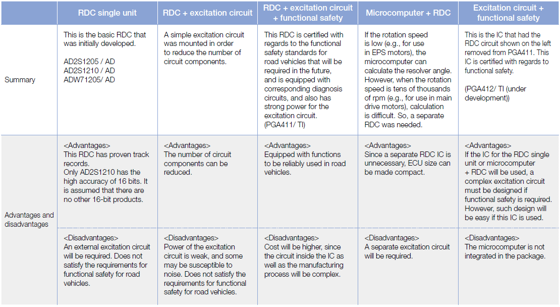
Types of R/D Converters
*Not sold by NMB Technologies Corp.
Glossary
Resolver: Analog converter that converts the rotor’s mechanical rotation angle into electric signals based on electromagnetic induction.
VR Resolver: Variable reluctance type resolver.
Primary winding: Input winding (input side).
Secondary winding: Output winding (output side).
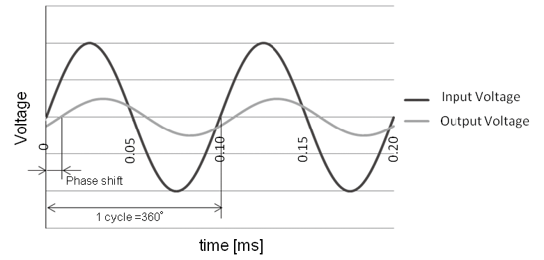
Input voltage: Voltage applied to the primary winding.
Output voltage: Voltage induced in the secondary winding.
Rotor: Rotary component attached the motor shaft.
Stator: Fixed component composed by Winding, stack, lead wire, connector, etc.
Rotor Lobes: Wave shape for the Rotor outer diameter.
Number of multiple: Value that shows the number of electric signal cycles that will be output when the rotor makes one revolution.
Transformation ratio: Ratio of maximum output voltage to input voltage.
(Transformation ratio = maximum output voltage / input voltage)
Phase shift: Shift in time of output voltage to input voltage.
Angle accuracy: Maximum error when the mechanical angle is 360°.
Input frequency: Frequency of the input voltage applied to the primary winding.
Input impedance: Minimum impedance at the input side.
Output impedance: Maximum impedance at the output side.
R/D (Resolver to Digital) conversion IC: Converts resolver signals into digital absolute position angle signals.